

Using the device, you can remotely android control RGB LED strip (or RGB LEDs) via any Android device with an integrated Bluetooth module.
A distinctive feature of this project is the simplicity of the hardware and software part of the system, which includes a Bluetooth controller, a portable Android device with an installed application (smartphone, tablet) that functions as a remote control.
The Bluetooth controller is a compact device consisting of an Atmel ATmega8 AVR microcontroller (MC), a miniature HC-05 Bluetooth module, N-channel power MOSFET switches, integrated voltage regulators, status LEDs, and several passive elements.
Main characteristics of the system:
- easy and sufficiently informative graphical user interface;
- displaying the MAC address of the connected Bluetooth controller;
- possibility of manual setting of MAC-address;
- service messages about errors of connection with the Bluetooth controller;
- buttons for quick selection of the color;
- possibility of manual setting of colors;
- information about the connection status;
- the possibility of increasing the functionality (you will need to upgrade the microcontroller program).
- hardware (Bluetooth controller):affordable, cheap and easy to use Bluetooth module HC-05;
- implemented on MK 3 channels of 8-bit PWM for LED control;
- N-channel MOSFETs in a case for surface mounting are used as power switches;
- autonomous work – no need for constant communication via Bluetooth with an Android device;
- communication range 10-15 m;
- supply voltage 12 V;
- current consumption of the Bluetooth controller (without LED strip): – Bluetooth module in the search mode: 55 … 60 mA;
- with an established connection with an Android device and no commands: 22 … 27 mA;
- reception and processing of the command: 38 … 42 mA;
- two LEDs to indicate the operating mode of the Bluetooth controller;
- the ability to implement 10-bit PWM control;
- the ability to implement control of various lighting effects;
- simple application for an Android device: the HC-05 Bluetooth module connects to the ATmega8 via the UART interface (ports PD0 / RXD and PD1 / RXD). Two LEDs D1 and D2 inform the user about the current operating mode of the Bluetooth module (search, connection establishment, AT command mode).
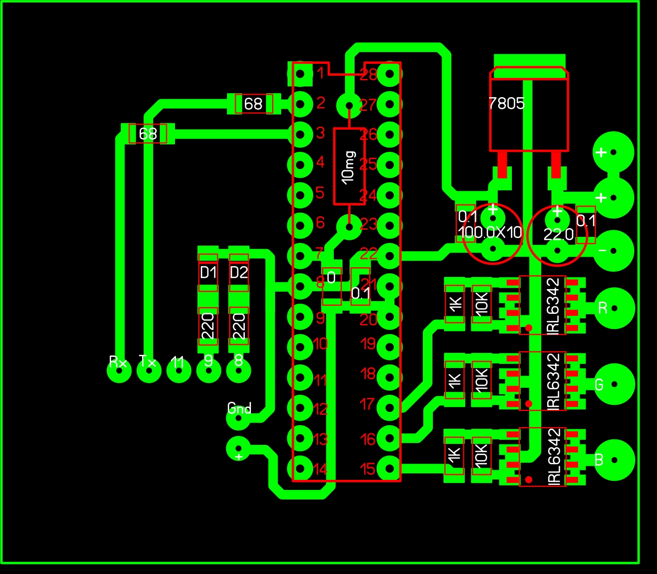
Schematic diagram
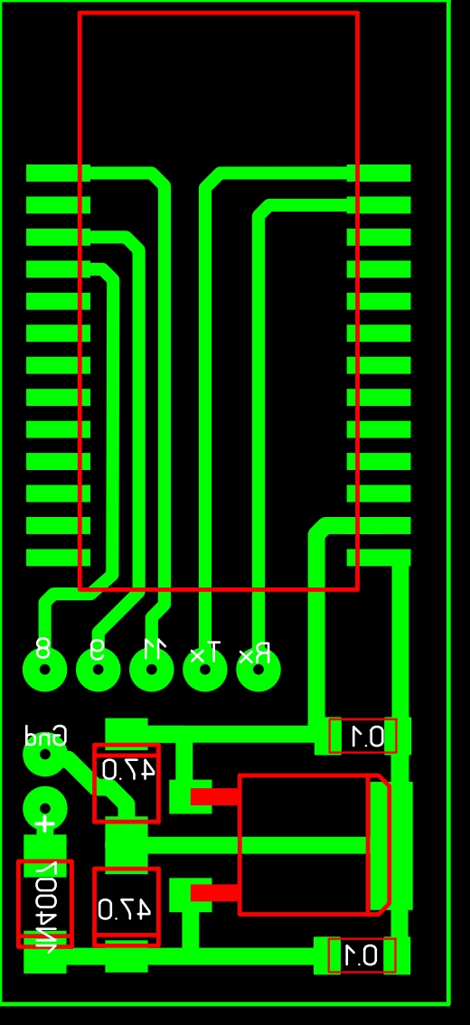
Printed Circuit Board PCB ( android control RGB LED strip)
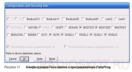
 Fuses:
Download Files:


